


New early VDO-style Type 3 tachometer with red needle. 12 Volt. Fits in place of the original clock.
Tachometer does a full sweep and resets to ZERO when powered.
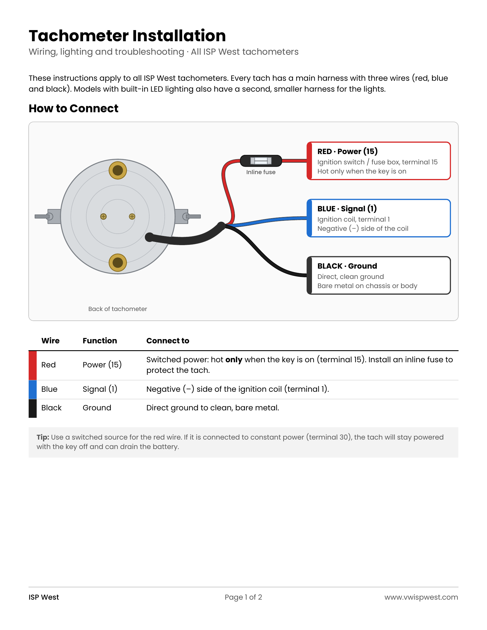
How to Connect:
- RED is Keyed Power (15)
- Blue is Signal (1)
- Black is Ground
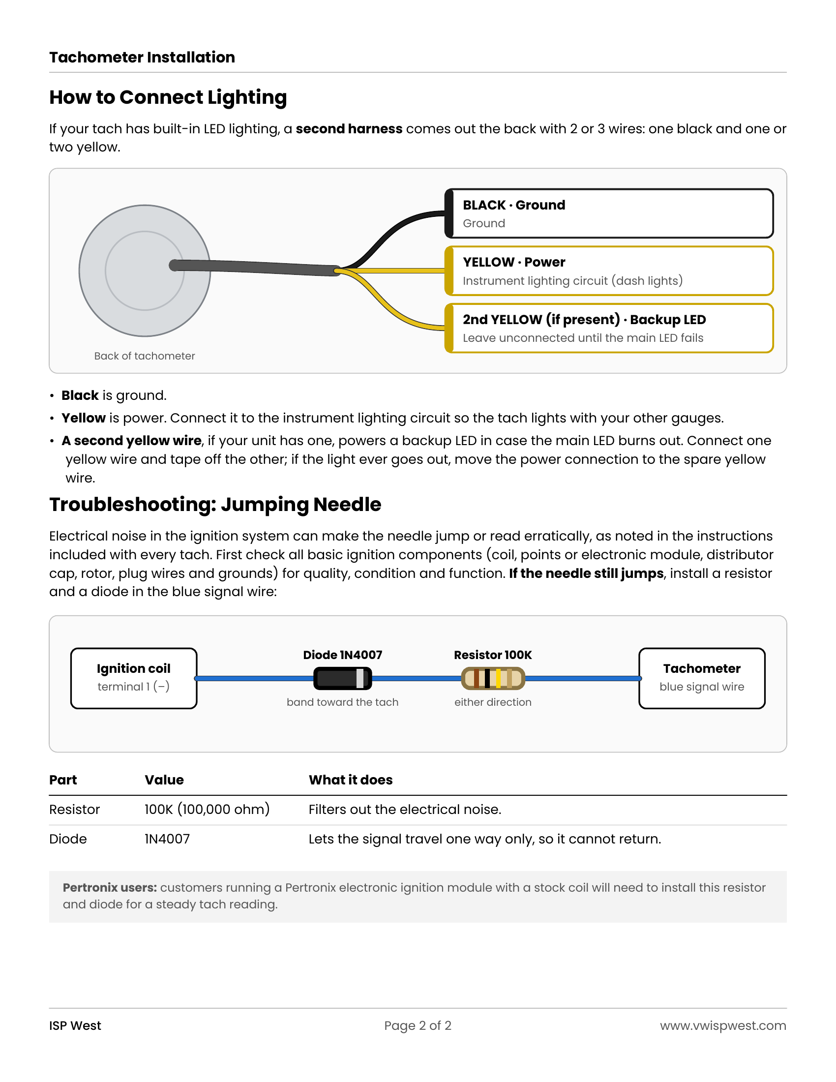
Troubleshooting: Jumping Needle
If all basic ignition components are functioning properly and the needle is still jumping, installing a resistor (100K) and diode (1N4007) to the signal line is required.
Customers with Pertronix modules and stock coil will need to install the diode and resistor.
Installation instructions and wiring diagrams are on the Instructions tab.
Installation instructions and wiring diagrams for ISP West tachometers. Click a page to open it full size.
 Warning: Cancer and Reproductive Harm. www.p65warnings.ca.gov
New early VDO-style Type 3 tachometer with red needle. 12 Volt. Fits in place of the original clock.
Tachometer does a full sweep and resets to ZERO when powered.
How to Connect:
- RED is Keyed Power (15)
- Blue is Signal (1)
- Black is Ground
Troubleshooting: Jumping Needle
If all basic ignition components are functioning properly and the needle is still jumping, installing a resistor (100K) and diode (1N4007) to the signal line is required.
Customers with Pertronix modules and stock coil will need to install the diode and resistor.
Installation instructions and wiring diagrams are on the Instructions tab.
Installation instructions and wiring diagrams for ISP West tachometers. Click a page to open it full size.

Be the first to review this product!
Share your experience to help other VW enthusiasts make the right choice.


